Polygon Turning Explained
I came across this video on YouTube a couple days back. As a novice machinist I was initially very confused - aren’t lathes supposed to be used to turn parts into axial-symmetric shapes? How is it possible to make, say a hexagon, with an engine lathe?
Ok, I get that you’ll need two spindles (part spindle, and live tooling spindle) that somehow are synchronized together, but how exactly can you produce a flat surface, given that both the part and the cutter are spinning, tracing out curves instead of straight lines?
I checked Wikipedia, and found a page on this subject. However it isn’t very well written and doesn’t actually explain how it really works.
To figure out what is really going on in polygon turning, it’s best to visualize the path traced out by the tips of the cutters. But the part being cut is also rotating, you say. Then let’s work in a non-inertial frame co-rotating with the part spindle. In this reference frame the part is stationary, but the motion of the cutters is slightly more complicated. The center of the cutter wheel is rotating around the center of the part with angular speed , while the cutter wheel itself is rotating with angular speed . The tips of the cutters would trace out a curve much like epitrochoids, but not quite. Unlike epitrochoids, here the direction of the two rotations are opposite, .
With Mathematica it’s easy to visualize the curve. First, some explanation of tunable parameters is due. Let’s set the cutting edge diameter to be 1, and denote by the distance between the center of the part and the center of the cutter wheel. Then I will call the ratio of the two angular speed the revolution ratio. The number of (evenly spaced) cutters on the cutter wheel is denoted by .
The first example would be for turning a hexagon. See the code and plot below.
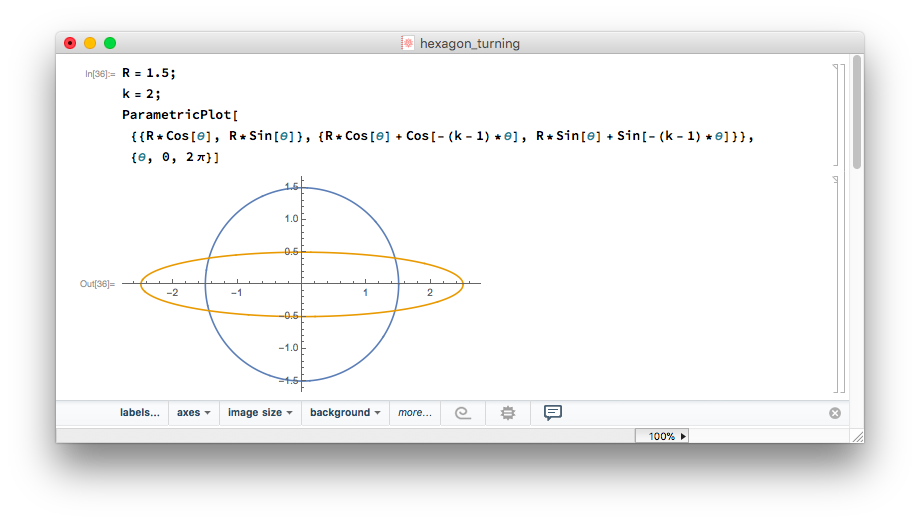
The blue circle marks the trace of the center of the cutter wheel, while the orange curve marks the path of the cutter tip. Note that the curve is everywhere convex. But the part closest to the origin looks almost flat. Now if we put three cutters around the cutter wheel, then the traces would be 120 and 240 degrees rotated, resulting in the curve shown below:
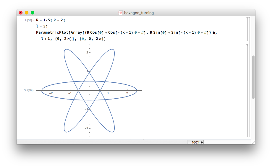
The three cutters indeed give you an approximated hexagon! Polygon turning is as simple as this! You can even do pentagons!
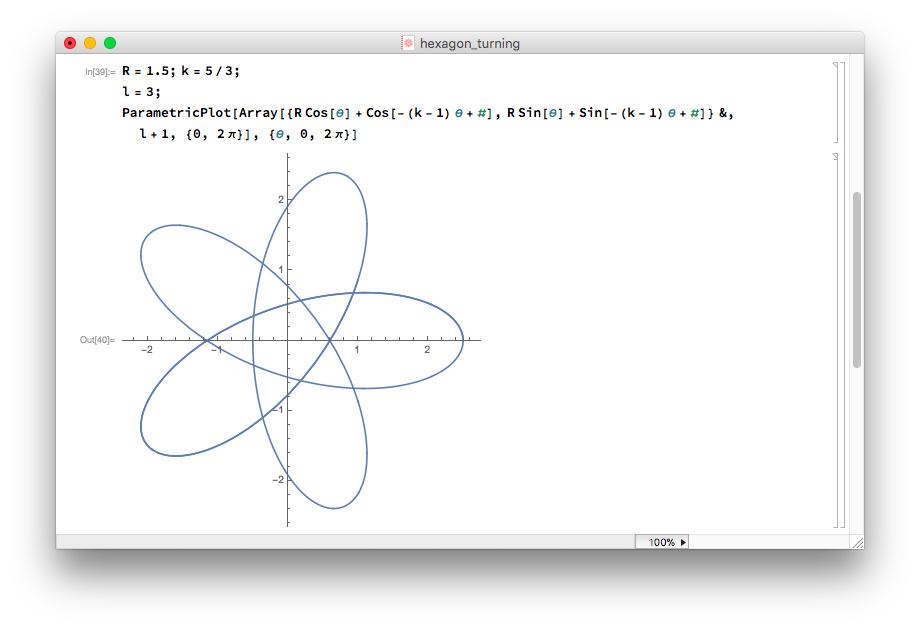
But how do you determine what revolution ratio and number of cutters for a given polygon? A good rule of thumb is have the number of faces . You still have the freedom to pick the integer . Say you want to turn a triangle, then you can either have , or , or . These different choices will result in different shapes of the “flat” face. A large will give you a convex face, while a small will result in a concave face. On page J23 of this catalog from Horn USA, general advice on what revolution ratio and number of inserts to be used can be found. Of course, you can calculate the exact resulting shape in Mathematica as I have just shown!
Please let me know if anything is unclear in my article, and thanks for reading!